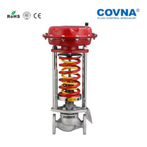


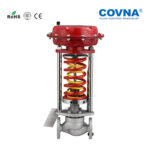
Self Actuated Pressure Control Valve
| In valve assembly | |
| seat material | Stainless steel |
| Flange standard | ANSI、JIS、DIN、GB、JB |
| texture of material | A3, A3 steel coated with tetrafluoroethylene Stainless steel filler: nitrile, Yibing, fluorine |
| Valve core material | Special hard seal (provided by users) – stainless steel (1Cr18Ni9Ti, 1cr18ni12mo2ti); (soft seal – stainless steel inlaid rubber ring) |
▋ Quick Details
| Valve body | In valve assembly | ||
| Nominal diameter | DN15-DN250 | seat material | Stainless steel |
| line type | flange | Flange standard | ANSI、JIS、DIN、GB、JB |
| Pressure class | PN1.6-PN6.4MPa | texture of material | A3, A3 steel coated with tetrafluoroethylene Stainless steel filler: nitrile, Yibing, fluorine |
| body material | (ZG1Cr18Ni9Ti、ZG1Cr18Ni12Mo2Ti) | Valve core material | Special hard seal (provided by users) – stainless steel (1Cr18Ni9Ti, 1cr18ni12mo2ti); (soft seal – stainless steel inlaid rubber ring) |
Self-operated pressure regulating valves are divided into three series: self-operated pressure, differential pressure, and flow regulating valves. The self-operated pressure regulating valve is divided into two types according to the position of the pressure taking point: before the valve and after the valve. When the pressure taking point is in front of the valve, it is used to regulate the constant pressure in front of the valve; When the pressure tapping point is behind the valve, it is used to regulate the constant pressure behind the valve.
Main parts and materials of self-operated pressure regulating valve:
Nominal diameter
Self-operated temperature regulating valves are divided into two types according to temperature:
Heating type
Working principle of self-operated temperature regulating valve
The temperature regulating valve works according to the principle of incompressibility, thermal expansion, and cold contraction of liquid. For the self-operated temperature regulating valve for heating, when the temperature of the controlled object is lower than the set temperature, the liquid in the temperature bag shrinks, and the force acting on the actuator push rod decreases. The valve core components open the valve under the action of spring force, increase the flow of heating media such as steam and hot oil, and increase the temperature of the controlled object until the temperature of the controlled object reaches the set value, the valve closes. After the valve closes, When the temperature of the controlled object decreases, the valve opens again, and the heating medium enters the heat exchanger to increase the temperature so that the temperature of the controlled object is constant. The valve opening is related to the difference between the actual temperature of the controlled object and the set temperature.
Cooling type
Working principle of self-operated temperature regulating valve.The working principle of the self-operated temperature regulating valve for cooling can refer to the self-operated temperature regulating valve for heating. Only when the valve core components are opened and closed under the action of actuator and spring force, as opposed to the temperature closing valve, the cold medium is passed in the valve body, which is mainly used for temperature control in the cooling device.
Working principle of a self-operated flow regulating valve.After the controlled medium is input into the valve, the pressure in front of the valve is input into the lower membrane chamber through the control pipeline, and the pressure throttled by the throttle valve is input into the upper membrane chamber. The data difference between the two is called the effective pressure. The thrust generated by the pressure in front of the valve acting on the diaphragm is balanced with the thrust difference generated by the pressure after throttling by the throttle valve acting on the diaphragm and the spring reaction force, which determines the relative position of the valve core and the valve seat, to determine the flow through the valve. When the flow through the valve increases, that is, the pressure difference increases. As a result, they act on the lower and upper membrane chambers respectively to move the valve core towards the valve seat, thus changing the flow area between the valve core and the valve seat and increasing the pressure difference, The thrust of the increased pressure difference acting on the diaphragm plus the spring reaction force and the thrust of the pressure in front of the valve acting on the diaphragm will balance at the new position to control the flow. On the contrary, the same is true.
The self-operated regulating valve is used to regulate the medium flow, pressure, temperature, liquid level, and other process parameters in the field of industrial automation process control. According to the control signal in the automation system, the opening of the valve is automatically adjusted to realize the adjustment of medium flow, pressure, temperature, and liquid level.
Main features of the self-operated flow regulating valve
1. The self-operated pressure regulating valve does not need additional energy and can work in a situation without electricity and gas, which is convenient and energy-saving.
2. The range of pressure sections is fine and cross each other, and the adjustment accuracy is high.
3. The pressure setting value can be set continuously during operation.
4. For the pressure regulation behind the valve, the ratio between the pressure before the valve and the pressure behind the valve is 10:1 ~ 10:8
5. Rubber diaphragm detection, high detection accuracy, and sensitive action of the actuator.
6. The pressure balance mechanism is adopted to make the regulating valve sensitive and accurate control.
▋ Packaging
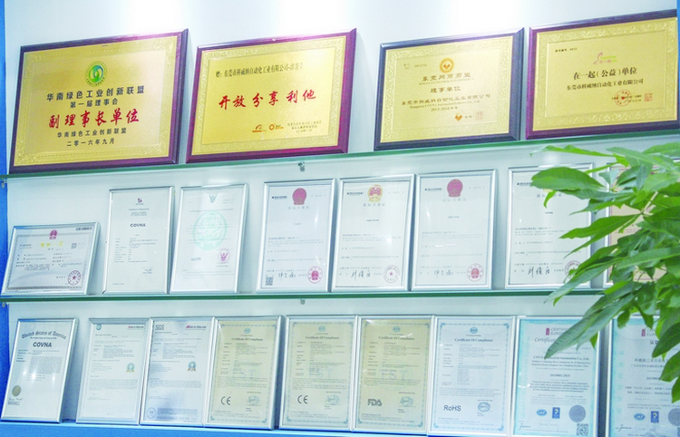
▋ Certification
▋ About COVNA
| Valve body | In valve assembly | ||
| Nominal diameter | DN15-DN250 | seat material | Stainless steel |
| line type | flange | Flange standard | ANSI、JIS、DIN、GB、JB |
| Pressure class | PN1.6-PN6.4MPa | texture of material | A3, A3 steel coated with tetrafluoroethylene Stainless steel filler: nitrile, Yibing, fluorine |
| body material | (ZG1Cr18Ni9Ti、ZG1Cr18Ni12Mo2Ti) | Valve core material | Special hard seal (provided by users) – stainless steel (1Cr18Ni9Ti, 1cr18ni12mo2ti); (soft seal – stainless steel inlaid rubber ring) |

